Beginner's Guide to the LINEAR CD4040BF: What It Is, Key Functions, and How to Get Started (2025)

Are you just getting started in digital electronics? Ever found yourself wishing you could easily count pulses, divide frequencies, or add a solid state “tally counter” to a project—without the complexity? If so, welcome! This guide was written precisely for total beginners, with the lessons I wish someone had shown me when I started out.
We’ll walk through what the LINEAR CD4040BF does, why it matters, and how you can build your very first binary counting project with confidence—no prior experience required. If you’re feeling a bit nervous about wiring your first digital IC, don’t worry. You’re definitely not alone, and everyone starts somewhere!
1. Why Digital Counters Matter (And Why the CD4040BF Is a Friendly First IC)
Digital counters are like tally clickers—they count incoming electronic "events" (like button presses or clock pulses) and convert them into a sequence you can read, use, or display. The LINEAR CD4040BF is a classic 12-stage binary ripple counter/divider IC that lets you do just that, handling frequencies and counts in a format that’s friendly for beginners and experts alike.
Why start here?
Super common: Found everywhere in clocks, timers, frequency dividers, and learning kits.
Easy to wire up: No programming required. Just supply power, connect the clock, and watch it count!
Learn real digital logic: Gain instant hands-on experience with binary counting, one of the building blocks of electronics.
2. What Is the LINEAR CD4040BF?
Think of the CD4040BF as a digital version of a row of coin counters. Each time you drop a coin (send a pulse), the IC counts it, updating its outputs to represent numbers—using LEDs or other displays.
Technically, it’s a 12-stage ripple carry binary counter. That means:
"12-stage": It can count up to 2¹² (4096!) before it rolls over.
"Ripple carry": Each stage (output) flips only when the one before it completes a cycle—just like a sequence of dominoes.
You feed it a pulsing signal (“clock”), and it divides that signal by 2, 4, 8, etc., at each output. Need to divide a frequency by 8? Just use output Q3!
If that sounds mystical, don't worry—a quick project will make it crystal clear.
Authoritative source: Texas Instruments - Official 2025 Datasheet
3. Understanding the Pinout (Visual & Table)
Connecting your first chip can feel intimidating—especially with all those tiny pins. The CD4040BF usually comes in a 16-pin package. Here’s a simplified visual and table so you’re never lost:
   +---+  CD4040BF Pin Layout  +---+
   | 1 | Q4      | 16 | VDD (+V supply)
   | 2 | Q5      | 15 | Q3
   | 3 | Q6      | 14 | Q2
   | 4 | Q7      | 13 | Q1
   | 5 | Q8      | 12 | Clock Input
   | 6 | Q9      | 11 | Reset (Active HIGH)
   | 7 | Q10     | 10 | Q12
   | 8 | VSS (Gnd)| 9 | Q11
   +-----------------------------+
Pin | Function |
|---|---|
1 | Q4 (Counter Output) |
2 | Q5 |
3 | Q6 |
4 | Q7 |
5 | Q8 |
6 | Q9 |
7 | Q10 |
8 | VSS (Ground) |
9 | Q11 |
10 | Q12 |
11 | Reset (active HIGH) |
12 | Clock Input |
13 | Q1 |
14 | Q2 |
15 | Q3 |
16 | VDD (+V supply) |
Tips for memory:
Pin 8: always ground
Pin 16: always supply (+V)
Outputs are scattered, but clock and reset are grouped near the middle (Pins 11 & 12)
For full PDF diagrams, see the official datasheet from Texas Instruments.
4. Tools & Parts Checklist Before You Start
Let’s keep it simple. For your first project, all you need is:
CD4040BF IC (or compatible 4000-series binary counter)
Breadboard
12 LEDs & 12 resistors (220–470Ω recommended)
Pushbutton switch or a 555 timer circuit (for clock input)
Power supply (5V–9V is safest; never go above 15V)
Jumper wires
(Optional) Multimeter or oscilloscope for advanced checking
Decoupling capacitor (10uF or similar) across power pins for stability
Quick Tip: Double-check voltage ratings before you plug in! CMOS ICs are sensitive—never exceed 15V, and watch out for reverse polarity.
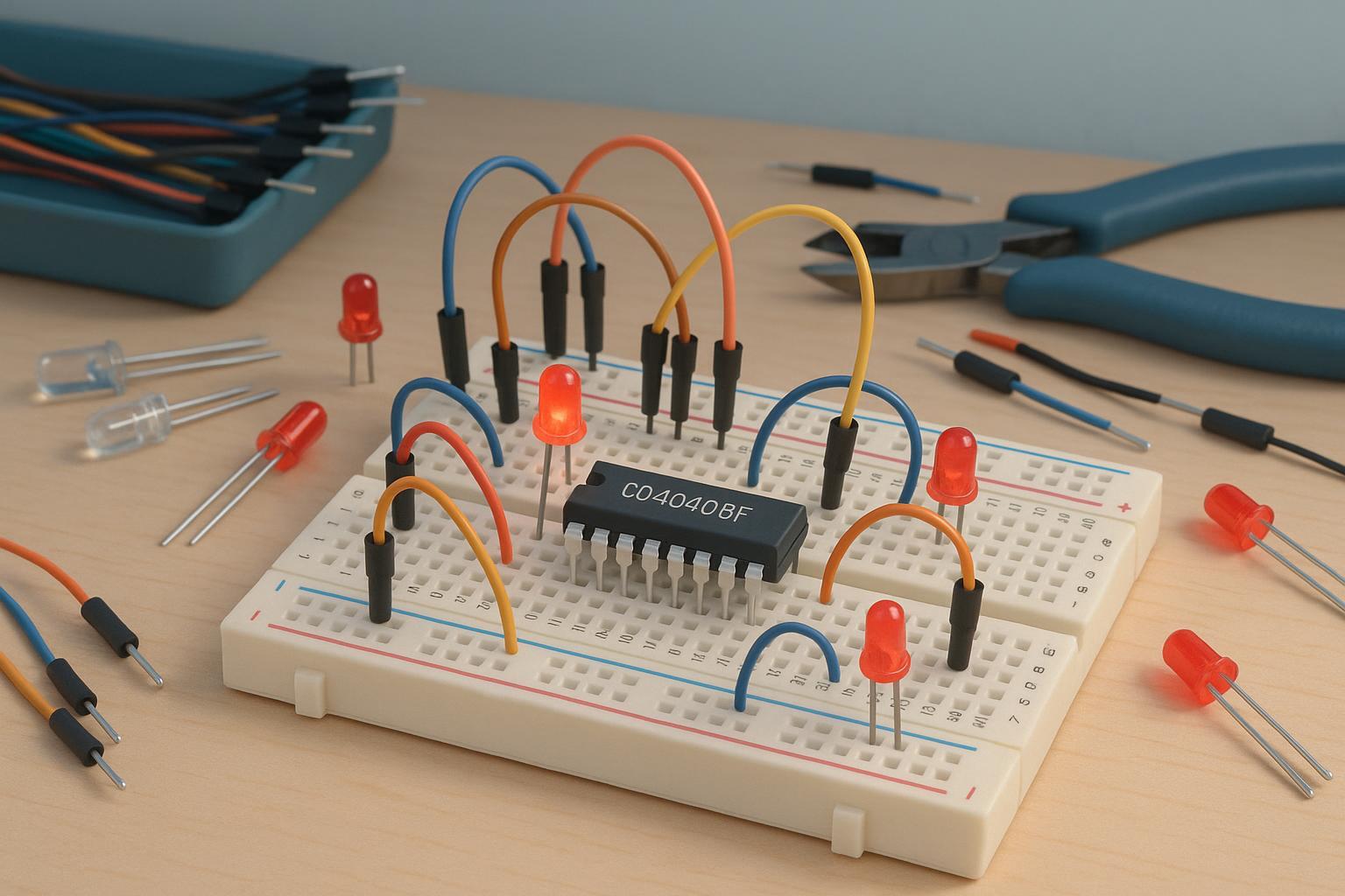
5. Step-by-Step: Breadboard Setup with the CD4040BF
Ready to build? Here’s a friendly walkthrough—picture each step and take your time.
Plug the IC into your breadboard, Pin 1 facing left.
Connect Pin 16 (VDD) to +5V to +9V, Pin 8 (VSS) to ground.
Attach your clock source to Pin 12:
Pushbutton: Wire with a pull-down resistor for single pulses (debounce with a small capacitor if available).
555 timer: Use its output for continuous pulses (great for automation).
Ground Pin 11 (Reset) to enable counting.
Optionally, connect a pushbutton to Pin 11 and VDD if you want to manually reset.
Connect outputs (start with Q1–Q4, Pins 13, 14, 15, 1) to ground through a resistor and LED each.
Power up! Press your clock button to step the counter and watch LEDs light up in binary sequence.
If your LEDs don’t light, don’t panic—see troubleshooting below!
If you’d like a breadboard schematic or see a project in action, check out this YouTube search for up-to-date video walkthroughs.
6. Your First Project: LED Binary Counter in Action
Now, let’s see your CD4040BF in action. You’ll see one LED light with the first pulse, two with the second, and so on. Each output divides the incoming signal by 2 further:
Q1: Output toggles every two clock pulses
Q2: Output toggles every four clock pulses
Q3: Output toggles every eight clock pulses
…and so on!
Want to get fancy? Replace your pushbutton with a 555 timer circuit, and your LEDs will pulse in sequence—an instant visual frequency divider. Try running simulations on Tinkercad Circuits for a stress-free digital sandbox.
7. Common Beginner Mistakes (And How to Fix Them!)
Mistakes are a normal part of learning. Here’s what beginners (including me!) often stumble over—and simple solutions:
Error | Why It Happens | How to Fix |
|---|---|---|
No LEDs light up | Power issue or wrong chip orientation | Check VDD/VSS connections, double-check pin 1 |
Nothing counts | Reset pin stuck HIGH | Tie Pin 11 LOW/GND, add pull-down resistor |
Erratic counting | Noisy/poor clock pulses | Debounce switch or use a 555 timer circuit |
Instant LED failure | No resistors in LED lines | Always use 220–470Ω resistors on outputs |
Chip hot/not working | Excess voltage or short circuit | Use 5V–12V, verify breadboard wiring |
Pro tip: Never leave unused inputs floating—tie them gently to VDD or VSS for stability.
8. Extend Your Learning: Where to Go Next
You’ve built your binary counter—what next?
Experiment with more outputs or try cascading multiple counters.
Check community forums like EEVblog or All About Circuits for inspiration and troubleshooting.
Always reference the latest CD4040BF datasheet for electrical specs.
Want more project inspiration? Try searching YouTube for "CD4040 breadboard beginner" tutorials.
9. Friendly Encouragement & Next Steps
If your first count didn’t work, if you felt overwhelmed by pin numbers, or if a mysterious wire came loose—don’t worry! Every electronics enthusiast (including pros) has been there. Your courage to jump in and experiment with the CD4040BF already sets you ahead of where I started.
Keep building, keep asking questions, and enjoy every light-up moment as you unlock new digital projects. When you’re ready, branch out into more counters, bigger sequences, or combine CD4040BF chips for even more complexity. The world of digital logic is yours to explore—one pulse at a time.
Happy counting!
Authoritative References & Resources
If you found this guide helpful, consider sharing it with a fellow builder or exploring new ICs on your next electronics adventure.